Focke Fulf Fw 190 D-9 Papagei
| Manufacturer: | Kit: | Quality: |
| Academy | Focke Wulf Fw 190 D-9 Papagei Staffel | |
|
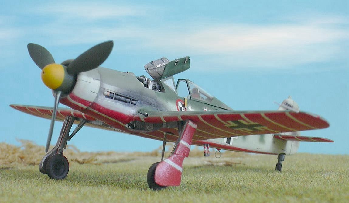
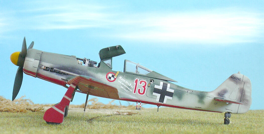
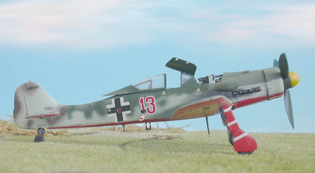
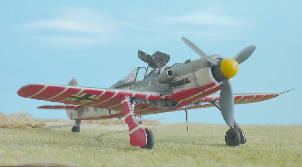
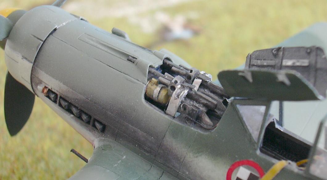
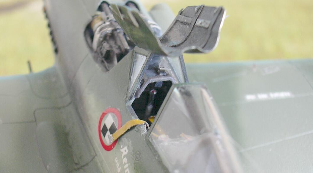
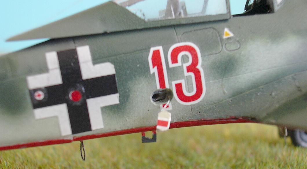
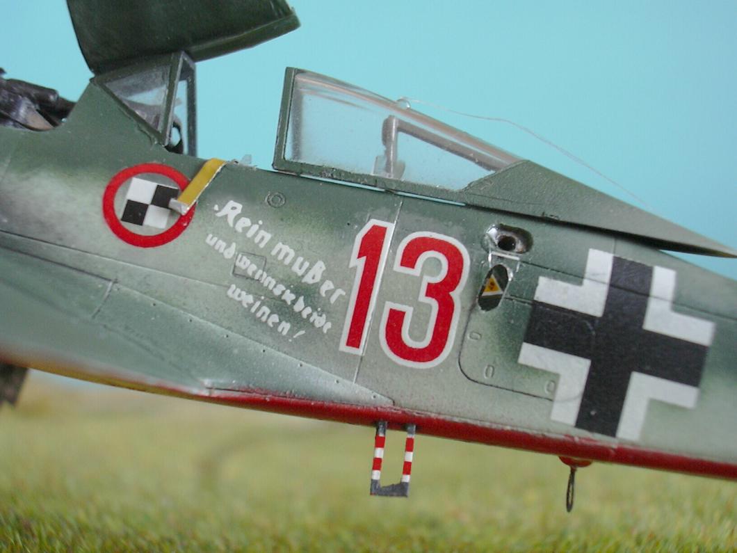
► Teil IV: Kennung, Fertigstellung Zur besseren Handhabung habe ich Rumpf und Tragflächenoberseiten noch getrennt lackiert. So konnte ich auch die anhand der Originalfotos nachgewiesene starke Verschmutzung entlang der Auspuffreihen anbringen, ohne daß mir die Tragflächen im Weg gewesen wären. Erst danach wurden Rumpf und Tragflächen "verheiratet" und die Unterseitentarnung mitsamt den Balkenkreuzen per Luftpinsel aufgebracht. Natürlich ging dabei wieder einiges schief, so daß ich hinterher zum Pinsel greifen mußte, um so manches wieder gerade zu bügeln. Allerdings, auch am Original ... siehe oben. Zur starken Verschmutzung erlaube ich mir noch eine Anmerkung: Die Papageistaffel wurde angeblich erst im April 1944 offiziell aufgestellt. Da bis zum 08.05.1945 nicht unbedingt viel Zeit zum Fliegen war, heißt das im Umkehrschluß, daß die Rote 13, im Vergleich zu den anderen Maschinen der Papageistaffel, sehr oft in Gebrauch gewesen sein muß. Die anderen "Papageien" weisen keine solch starke Verschmutzung auf. Ich vermute, daß die Rote 13 vor ihrem "Papageienleben" bereits woanders im Einsatz war, denn sie wurde 02/1945 produziert. Die anderen beiden Fw 190 D-9 der Papageienstaffel hatten zudem die gewölbte Kanzel (und das große Leitwerk?) der "spät" produzierten D-9er. Die vierte bekannte Maschine schließlich war eine D-11 und keine D-9. Von den abschließenden Arbeiten stellte sich das Anbringen der Abziehbilder als die leichteste heraus. Auch wenn's eine Futzelei war, die Schriften an den Oberseiten anzubringen - die Abziehbilder sind sehr dünn, schön gedruckt, und haften auch ordentlich. Die Wartungshinweise der Unterseiten sowie an den Fahrwerksklappen ließ ich weg - die waren schließlich mit dem Streifenmuster übermalt! Weniger leicht war es, die beiden geöffneten Tankdeckel herzustellen. Schließlich gelang aber auch das mit der Zinnfolie und einem scharfen Skalpell. Als extra Schwierigkeit war zu beachten, daß auf beiden Deckelchen ein Markierung drauf ist! Auf dem linken das gelbe Dreieck - aber nur zum größten Teil, unterer Rand und Oktanzahl gehören unter dem Deckel auf den Rumpf - und auf dem rechten ein Teil der Flugzeugnummer. Am heikelsten war aber die Befestigung beider Deckel am Rumpf. Ich habe dazu aus Zahnseide ein paar Fasern herausgelöst, und diese als Halterung der Deckel verwendet. Das Verkleben war nur mehr mit Hilfe von Lupe, Zahnstocher und Pinzette zu bewerkstelligen. Schließlich sind die beiden Teile im Maßstab 1/72 gerade mal noch 3,5mm x 2mm "groß". Und natürlich ist es mir gelungen, einen der beiden nach dem Ankleben auch noch zu verlieren, so daß ich diese Flohdressur noch ein drittes Mal machen mußte! Als Antennendraht diente mir diesmal bereits erwähnte Zahnseide. Die sonst übliche Angelschnur ist, obwohl extrem dünn, zu steif. Diesmal mußte die Antenne nämlich "hängen" (was auf vielen Originalfotos deutlich zusehen ist). Anders als bei den 190ern der A-, F- und G-Serie hat die D-9 nämlich keinen Antennenspanmechanismus mehr vorzuweisen. Nach 13 Monaten Bauzeit (inklusive der Zeit für Überlegungen hinsichtlich Einbau des E-Motors und Fotografieren des Baufortschritts - und um den Bau dieses Modells zu dokumentieren, habe ich von den über120 Fotos nur brauchbare behalten, nur ein Bruchteil davon wird auch zur Veröffentlichung gelangen) habe ich nun ein wirklich prima Modell in der Vitrine stehen. Was Academy hier um einen sehr guten Preis anbietet, reicht im Normalfall auch dem erfahrenen Modellbauer. Auch Anfänger dürften mit diesem Bausatz keine Schwierigkeiten haben. Leider hat sich herausgestellt, daß der E-Motor eigentlich für die Katz' ist. Da es mir "freihändig" nicht gelungen ist, Motor- und Propellerachse hundertprozentig in eine Flucht zu bekommen, läuft der Propeller nämlich nur, wenn man den E-Motor mit "Überlast" fährt. Ich habe kein Verbindungsstück bekommen, das flexibel genug wäre, den "Knick" auszugleichen. Nicht mal das verwendete Stückchen Isolierung eines Telefondrahtes ist weich genug. Somit wird sich die Demonstration eines laufenden Propellers nur aufs allernötigste beschränken, da die Gefahr eines Motorbrandes (im wahrsten Sinn des Wortes) einfach zu groß ist. << Teil I: Erste Schritte << Teil II: Elektromotor, Motor-Atrappe, Spornrad << Teil III: Rumpfbewaffnung, Bemalung |
► Part IV: Markings, Ffinish For a better handling of the kit during the assembling, I colored the fuselage and the wings each alone. So I succeeded in applying the heavy soiling along the exhaust pipes, as proofed in original pictures, without being the wings in my way. When this was finished, the fuselage and the wings were "married" and then the camouflage of the lower wing-side, including the crosses, were applied with the airbrush. Of course, thereby appeared some faults, so that I had to do some corrections with the brush for a better view. But, the original coloring ... remember earlier. I allow me some comment to this aircraft's heavy soiling: The Parrot-Squadron was told to have been lined up officially in the mid of April 1944. There was not much time to use these aircrafts for flying until May, 08., 1945, when the war was over. This means, the Red 13, must have been in heavy use compared to other aircrafts of the Parrot-Squadron. I think, the Red 13 was in use elswhere, before becoming a Parrot, it was already manufactured in February 1945. The two other Fw 190 D-9's of the Parrot-Squadron are equipped with the bulged canopy (and the taller fin?) of the "late" manufactured D-9's. The fourth aircraft of the Parrot-Squadron finally was a D-11 and not a D-9. To apply the decals was the easiest to do of the finally works. Although it was a tiny detail work, to place the stencils correctly on the upper sides - the decals were very thin, smooth, well done and adhered perfectly. Caused by the red and white stripes, the lower sides and the covers of the landing-gear had no stencils, these were painted over. A less easy work was to make the caps of the gasoline- and the oxygen-container. But I succeeded with some tin-foil and a truly sharp scalpel. The extra-difficulty was, that there were markings on each of the thwo caps! The yellow triangle on the left side - but only the upper part, lower part and octane-cipher belong to the fuselage - and on the right cap a part of the aicraft's number 13. The most difficult to do, was to attach the two caps to the fuselage. I pulled out some filament of dental-silk and used these for attachment. Only with the help of magnifier, tooth-pick and tweezers the glueing could be done. These parts have "measures" of 3,5mm x 2mm in the 1/72 scale. And - of course - I succeeded in losing one of the caps when I was trying to glue it, so I had to do this flea-training once again. The already mentioned dental-silk became this time the antenna, too. The usual fishing-line would be much too unflexible, although it's extremely thin. On this aircraft the antenna must hang loose (what can be seen clearly on many pictures of the original aircrafts). Other then the A-, F- and G-190er's, the D-9's lacked the stressing-mechanism for the antenna. After having spent 13 months with assembling (including the time it took to study the different possibilities of the electric-engines' insertion - and the time for taking more than 120 pictures in order to show the assembling-progress, although only some of them will be published) now I ow a truly excellent model in my show-case. What Academy offers us with this kit for a good value, is truly good enough for the experienced modeller, too. But also beginners can succeed whit it. It's a pity, that the electric-engine was installed to no purpose, so it was proofing when the kit was finished. Offhand I did not succeed in installing the engine's axle correctly and strictly straigth with the propeller-axle. So the propeller can just be turned around, when running the electric engine with heavy overload. I was not able to find a junction felxible enough to equalize the angle. Not even the piece of telephone-wire-insulation, which I used as this, is smooth enough to do the function. So each demonstration of a rotating propeller must be restricted to the minimum, because of the danger of a burning engine (in the true meaning of the word). << Part I: First steps << Part II: Electric engine, engine-fake, tail-skid << Part III: Fuselage guns, camouflage |
Further pictures